Top Page Research Topics
 Biped Robot Robotic Wheelchair Mobile Robot Redundant Robot Robot Arm
Papers Staff Link Local Area::
Local Page
Local Link:
CIST Homepage CIST-OESE e-Learning
 CIST Portal
Contact:
Oda Laboratory
758-65, Bibi, Chitose
Hokkaido, 066-8655, JAPAN
Contents
Biped Walking Robot
Laser Sensor or Vision Sensor Based Walking Motion Control
We are developing a biped motion system. For certain stabilty of biped motion, the recognition of the relationship between robot and ground is one of important issues. We are now developing the laser or vision sensor based sensing system for biped robot.
Hardware Specification)
12DOF, 12 DC Motors( 60W X 12: SANYO DENKI Super-L & V),
Motor Driver: TITech Driver PC-0121-1 x12(Current Control),
Gear: Harmonic Gear(2x 1/120 , 4x 1/100 per leg, HDS CSF Unit-Type),
Weight: approx. 35Kg,
Sensor: Laser Distance Sensor(LK-500,Keyence) & Acceleration Sensor(Analog Devices) & Vision Sensor(Flea2,Point Grey Research) & Force Sensor(Minebea),
CPU: Pentium4 2.8GHz (External PC),
OS: Fedora 9 RT-Preempt Linux( RT-Preemption Patched Kernel),
Network Boot without HDD(PXE Boot),
I/O Interface: 16chAD/DA/Enc. 07-0003-01 General Robotix Inc.,
System Structure MapBlock Diagram of Motion Controller2012-2013, Updated...
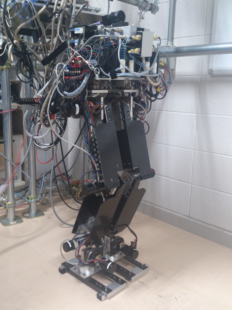
Main Material: Carbon FRP (CFRP) Force Sensor: OPFT-1kN-CH-C, MinebeaVision-based Balance Control for Biped Walking Robot
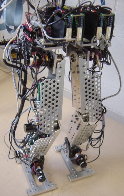
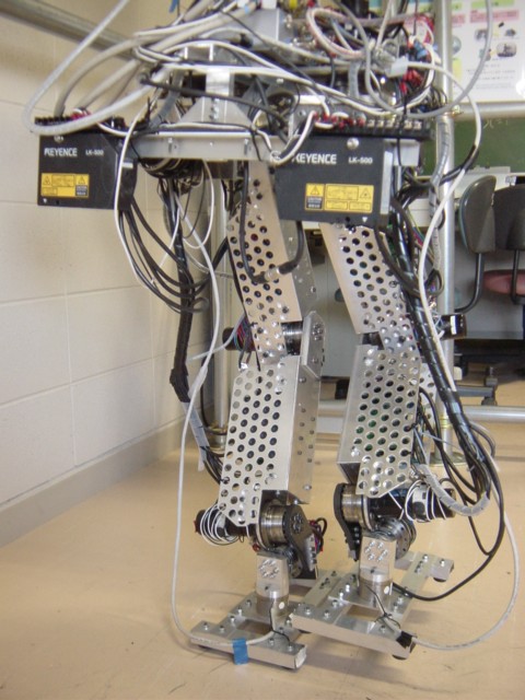
Our robot has some mechanical flexibility in ankle joint system. Our control approach actively utilizes the deflections at ankle for detecting the ZMP(Zero Moment Point). The deviated center of gravity (COG) due to the ankle's deflections is measured in real-time by laser distance sensor mounted on the hip. Assuming the two mass model at COG, the equivalent reaction force relating to COG deviation is used as feedback signal for ZMP stabilization.Fig.1-2 shows the laser-based walking robot. In our approach, ZMP can be detected by Laser Sensor or Vision Sensor instead of force sensing. We are also trying to replace the sensors into vision sensor for motion stabilization as shown in Fig.1-1(b).Fig.1-3 and Fig.1-4 show the successful walking and compliant response respectively. The force sensor is completely not used for controlling the dynamical balance in our vision-based approach.
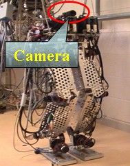
(a)Laser Sensor (b)Vision Sensor
Fig.1-1 Sensor System for Stable Walking
Fig.1-3 Movie of Vision-based Walking of Biped Robot
Vision-based Walking Direction Control
The tortional deflection around yaw axis at supporting ankle joint is intentionally generated for walking direction change. This means that the reaction torque due to the upper body rotational motion causes the tortional deflection at ankle joint while walking motion, and it can be proportionally modified by visual feedback regulator in order to change the walking direction. The camera system is mounted on the robot(Fig.1-1(b)), and the obtained image is used for detecting the target object and regulating the reaction torque in image-based visual feedback manner. The advantage of this idea is that the modification of COG and swing foot motion is not required for changing the walking direction. Although the quick turning motion is impossible in this idea, it is meaningful for the following walk to the target, or easy approaching to the destination without the trajectory planning.
Fig.1-6 shows the moving picture of walking direction control. The rectangle plate in the image is a visual target object as the destination.
Robotic Wheelchair(Electric Wheelchair)
Power Assisting Control by Visula Feedback
The electric wheelchair is one of promising devices as human supporting for aging society. And several capabilities can be implemented by using the robot technology, such as power assist function, intelligent navigation for safty and easy handling.
In our approach, the combination method between force-sensorless power assisting and visual sensing has been proposed for implementing both the power assisting and the operational guidance. This approach using vision-based power assisting control makes it possible to facilitate sophisticated interactions between human driving force and dynamic environments such as human following assist, obstacle avoidance and so on.
Fig.2-1 shows the moving picture of the wheelchair motion under our power assisting. In our method, We define the visual sensitivity which can be arbitrary regulated against moving object in environment, and its affected virtual force is transmitted through the driving human force.
Hardware Spec.)
AC Direct Drive Motors(x2) in Wheels(Wacogiken),
Weight: approx. 85Kg,
Sensor: Stereo Vision Sensor(Dragonfly2 x2,Point Grey Research),
CPU: Core2 Duo 3.0GHz for ImageProcessing WinXP PC & PentiumM for RT-Linux Motor Controller,
I/O Interface: AD/DA&Encoder Counter Board (PCI-3523A& PCI-6204 Interface Inc)
System Structure Map
Mobile Robot
Hardware Spec.)
CPU: Celeron 600MHz(PFM-F620S(AAEON), PC-104 Board Computer), OS: RT-Linux ( It is customized RedHat-Linux),
Disk: Compact Flash DISK 128MB, Network: 11Mbps Wireless LAN Sensor: Color CCD Camera, Photo Distance Sensor, Battery: 12V 2600mAh, Motor: 540Series(Mabuchi) armature current can be controlled by DA output. Steering: Steer angle is controlled by DA output, I/O Interface: PC-104 MPC104-DAC12
System Structure Map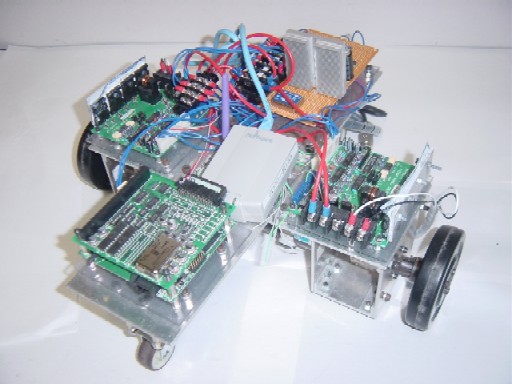
Hardware Spec.)
CPU: Arm Proccessor(Armadillo, PC-104 Board Computer), Motor Driver: TITech Driver PC-0121-1 x2(Current Control), OS: Embedded Linux,
Disk: Compact Flash DISK, Network: 11Mbps Wireless LAN through converter, Sensor: Color CCD Camera, Battery: 12V 2600mAh, Motors(x2): Super-L L402-011EL8 SANYO DENKI Inc., I/O Interface: PC-104 MPC104-DAC12, Gear: planetary gear 1/33
System Structure MapRedundant Manipulator
This topics involves a robust control method of kinematically redundant manipulator in order to distribute the motion controller into the simple components. In the redundant system, the flexible utilization of the redundancy is important to realize the dexterous motion such as obstacle avoidance, optimal configuration, highly manipulability and so on. Recently the several robust control strategies using disturbance observer have been proposed, and make it possible to realize the angular acceleration control of each actuator.
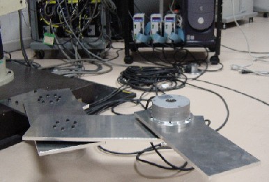
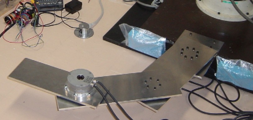
Spec.)3DOF Planar Redundant Manipulator,
AC Motors(x3)(FHA-25C-100,FHA-17C-100/50,Harmonic Drive Systems),
Sensor: PSD(Hamamatsu Photonics)&External Vision SONY CCD Camera
OS: Core2 Duo 3.0GHz for ImageProcessing WinXP PC & Pentium4 for Real-time OS VxWorks5.4,
I/O Interface: AD/DA&Encoder Counter Board (PCI-3341(DA Board)&PCI-3135(AD Board)&PCI-6205(Counter), Interface Inc)
System Structure MapIn these method, the disturbance acceleration or torque is estimated and suppressed by its feed-back. One of the inverse kinematics calculation in the redundant manipulator is mathematically resolved through the least-norm minimization. This means that the generalized inverse matrix and null space vector of Jacobian are used for the transformation from the desired workspace acceleration into the joint angular one. In another approach, the use of the augmented Jacobian matrix is convenient way to deal with the user-defined additional task for the utilization of the redundant motion. And its calculation process becomes simple algorithm in the same way as non-redundant systems. However, in these approach mentioned above, the motion controller of the redundant manipulator sometimes falls into inflexible control law for only specified tasks through the redundancy resolution. That is to say, the flexibility of the task selection which decides how to use the redundancy is not considered in the motion controller. And it causes the difficulty of the planning of the redundant motion, even though there are capability that the redundancy contributes to the dexterity and multi-behavior functions like human arm. This research is focused on such practical complexity and difficulty of the redundant system to implement the autonomous selection of the appropriate user-defined task vector according how to use the redundant degree-of-freedom now. Currentrly we are trying to use Optical Sensing Device for Force Based Motion Control. Following Moving Picture shows a compliant motion control using natural stifness of whole manipulator. That is to say, whole of manipulator works as force sensor by measuring torsional deformations.
Fig.4-2 shows the hybrid motion controller including both the posture controller by the optical flow feedback and end-effector motion controller by using encoder signal. In this method, the null space damping for posture stabilization is achieved by visual feedback, and the avoidance capability against the obstacle can be simultaneously considered.
Visual Feedback Robot Arm
The recent development of visual image processing is making possibility to realize the real-time motion tracking by visual servoing. In the visual servoing, several constraints between the mechanical structure of the manipulator and the vision sensor coordinate exist according to the algorithm of the target visual image processing. Furthermore, the tracking performance depends on the image processing speed, accuracy and the kinematic characteristic mapped on the image space. In the practical point of view, the visual motion to get the desired image area obtained by visual sensor is applicable to various kind of robot systems such as manipulators, mobile, walking robots and so on. Therefore, the development of the image processing technique and speed will make remarkable progress in industrial field and brings highly contributions on the robot system. So it is expected to consider and extend the robust motion controller based on the visual image space for the optimized configuration of the motion distribution. Currently we are using the PSD sensor (Position Sensitive Detector) for real-time processing to develop the motion controller based on image plane. In our approach, the workspace observers is directly applied in vision space. Then the dynamical manipulability is considered on the visual plane. And we are planning to develop the weighting approach of the image processing area related to desired motion.
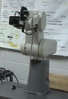
Spec.)5DOF Industrial Robot Manipulator(Mitsubishi Move Master),
Actuators: DC Motors(x5),
Sensor: PSD(Hamamatsu Photonics Inc.)
Motor Driver: PMA4&PMA2 ServoTechno, OS: VxWorks5.4,
I/O Interface: AD/DA&Encoder Counter Board (PCI-3155(AD)&PCI-3310(DA)&PCI-6201(x2,Counter),Interface Inc.)